Language

Schematic diagram

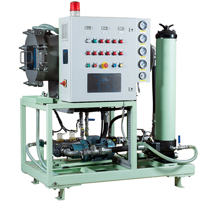
The contaminated oil is pumped out of the system by the inlet pump P01 through the inlet isolation valve MV01 and the oil suction filter FL01. When the pump inlet vacuum reaches -0.8Bar (the inlet filter is blocked or the inlet valve is not opened), it should be shut down and checked before it is normal. Normally, the oil enters the upper part of the vacuum container through the heating tank HE01 and the window SF01, and is sprayed out through the nozzle to form a stable oil film in the vacuum tank. The oil falls into the bottom of the container due to gravity, and the gas and moisture are removed from the top of the container. In order to maintain a stable vacuum, the air in the container is drawn out by the vacuum pump P03, and the outside air enters the container after being filtered by the side air filter PI01. The air with low relative humidity and the polluted oil flow form a large area of oil film to flow through. Because the water vapor pressure in the polluted oil film is much greater than the vapor pressure in the air, a large amount of water in the oil vaporizes. The vacuum pump P03 generates a stable vacuum in the container, thereby obtaining air with low relative humidity. When the outside air is sucked into the container through the manual valve MV04 of the PI01 level on the side of the air filter, its volume can be expanded 3-10 times according to the vacuum setting of the container, resulting in a decrease in its relative humidity. The vacuum of the container also causes the dissolved gas and other gases in the oil to escape and be pumped out to the atmosphere. At any time, if the vacuum of the container drops to -0.45Bar, the system will shut down. This set value can be modified by the customer according to the specific application to obtain the best efficiency. The oil that sinks at the bottom of the container is pumped out by the outlet pump P02 through the outlet filter FL02, the one-way valve CV01 and the outlet isolation valve MV02, and then leaves the oil purifier.
outline drawing

technical parameter:

VKVP series ordering information
VKVP □ □-□
Table 1 Table 2 Table 3
Filter element options:VER8314KS☑H
Table 1
Table 1 Flow options
Code | flow L/min | Filter code |
70 | 70 | 26 |
100 | 100 | 32 |
200 | 200 | 39 |
Function of the device:
Code | Viscosity |
A | <100cst |
B | ≤100cst~320cst |
C | ≤320cst~460cst |
Function of the device:
Code | Explosion-proof grade |
standard | none |
DIICT4 | DIICT4 |
... | ... |