Language

Technical index
1.1 The relationship between the output flow and viscosity (please refer to Table 2-1)
The flow rate and viscosity have the following relationship:
name | Oil viscosity mm²/s | |||
5±2 | 15±5 | 50±10 | 300±50 | |
flowL/min | 60 | 50 | 45 | 25 |
cleanliness level | NAS1638 Level 3 | |||
2-1
Note:① The output flow decreases with the increase of oil viscosity;
② In order to change the output flow, the outlet pressure can be changed, but it is also affected by the viscosity.
1.2、Ability to remove free water in oil:
If the content of free water in the unpurified oil is less than 0.25%, the mass content of free water in the oil after circulating purification is not more than 0.05% (that is, less than 500 ppm).
1.3、Pressure of the equipment
●The maximum output pressure is not more than 0.40Mpa;
● The minimum working pressure is not less than 0.15Mpa;
● The minimum setting pressure of the pressure switch should not be less than 0.13Mpa.
1.4、The leakage of graphite sealing device is not more than 20cm3/h.
1.5、When the unit starts to work, the volume of oil filled is no more than 18 liters.
2、The basic working principle of VKLP unit (please refer to Figure 3-1)

Figure 3-1 principle diagram
1. Oil tank 2. Oil outlet pipe 3. Oil suction pipe 4. Pipeline 5. Regulating valve 6. Pressure gauge
7. Sampling switch 8. Pressure switch 9. Electric motor 10. Contamination box 11. Booster pump
12. Centrifugal cartridge assembly 13. Vacuum pump 14. Liquid level controller 15. Auxiliary oil tank
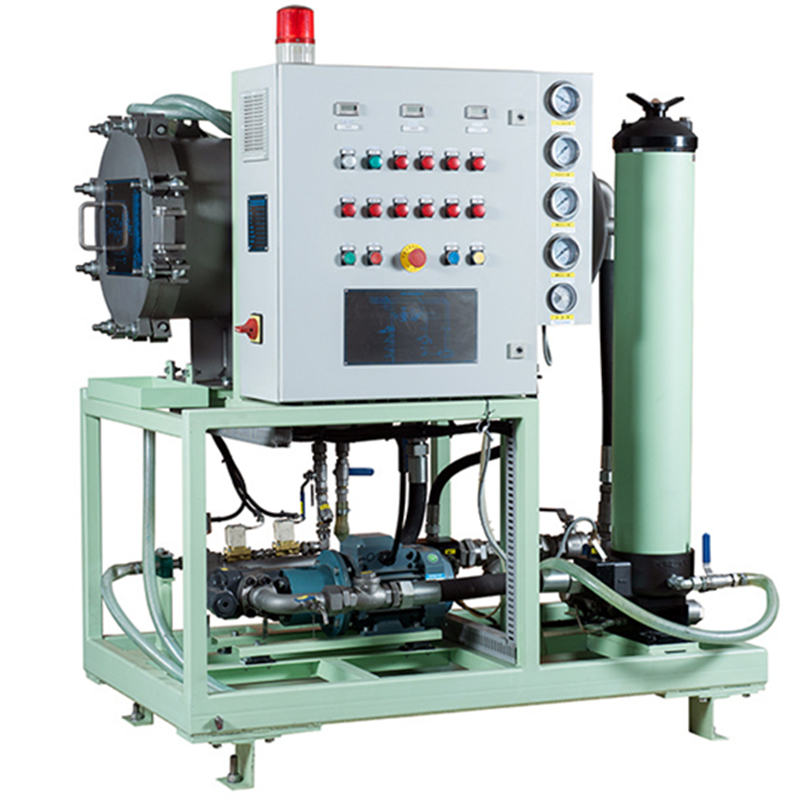
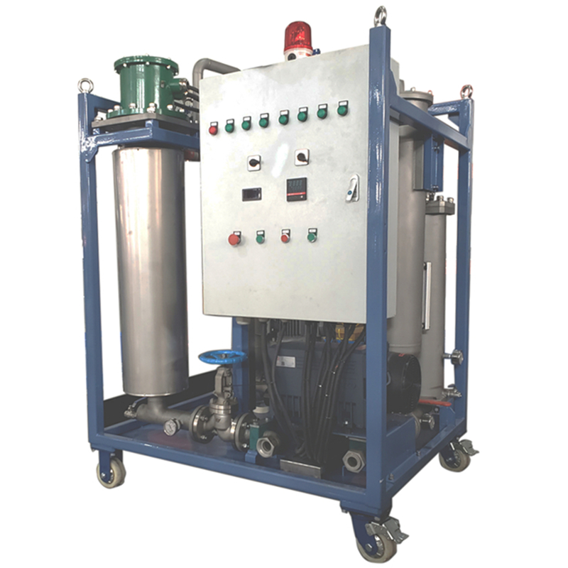
3、Composition
3.1、The main components
Car body, electric motor, centrifugal cylinder assembly, vacuum circuit assembly, dirt receiving box, instrument panel, electric control box, hydraulic pipeline, four damping wheels, etc.
3.2、Centrifuge tube assembly

Figure 3-1 The structure of the cartridge assembly
It is composed of a front end cover, a cylinder, a central shaft assembly, an oil collecting impeller, a reinforcing frame and other elements. The centrifuge cylinder and the front end cover are fixed together by a snap ring. They are supported on the central shaft assembly by upper and lower guide sleeves, and the front end cover is The reinforced frame is connected, and the bowl-shaped plastic parts are superimposed on the frame. The plastic parts are squeezed together by the cylinder body and the front end cover. When the front end cover is driven by the pulley to rotate at a high speed, the purified oil is sucked into the centrifuge cylinder and discharged after purification.
3.3、Contamination box
When the centrifuge drum rotates at high speed, the contaminants in the oil are thrown on the wall of the drum. After the centrifuge drum stops rotating, the contaminants attached to the wall of the drum under the action of gravity are deposited in the dirt receiving box.
3.4. Dashboard (please refer to Figure 4-3)

Figure 3-3 Schematic diagram of the dashboard
The instrument panel is equipped with a pressure regulating switch, a system pressure gauge, a sampling switch, a start and stop button for the centrifugal cylinder motor, a rotary switch for the vacuum pump motor, and a signal light.