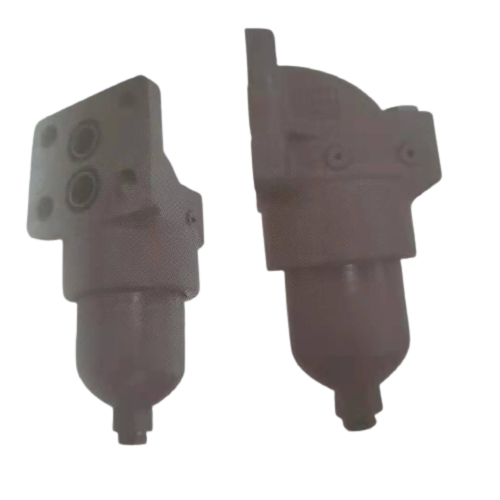
VKZH pipeline type high pressure filter series

1. Model description: VKZH pipeline high pressure filter
Table 1 Nominal pressure of filter
Code | 压力等级 |
E | 22MPa |
H | 32MPa |
Table 2 Nominal flow rate of filter
Code | instruction |
10 | 10L/min |
25 | 25L/min |
40 | 40L/min |
63 | 63L/min |
100 | 100L/min |
160 | 160L/min |
250 | 250L/min |
400 | 400L/min |
630 | 630L/min |
800 | 800L/min |
Table 3 Oil port passage
Code | Types of |
15 | The way to15 |
20 | The way to20 |
25 | The way to25 |
32 | The way to32 |
40 | The way to40 |
50 | The way to50 |
53 | The way to53 |
Table 4 Filter accuracy
Code | Precision |
003 | 3um |
005 | 5um |
010 | 10um |
025 | 25um |
Table 5 Filter material
Code | Material |
G | High-efficiency glass fiber |
W | Stainless steel wire mesh |
Table 6 Differential pressure alarm device options
Code | Types of |
B | Plug |
M | Electrical switch, single pole double throw |
Table 7 Sealing material options
Code | Types of | Use medium |
H | Nitrile rubber | Petroleum base, water-in-oil emulsion, water glycol |
Z | fluororubber | Dedicated synthetic fluid |
Table 8 Installation form
Code | Types of |
无 | Threaded connection |
F | Flange connection |
B | Plate connection |
DL | Flip tube |
DF | Flip flange type |
DFA | Flip flange type A |
DFB | Flip flange type B |
BD | Flip-chip |
Selection example VKZH100DN005GMHDL
Indicates the inverted tubular high-pressure filter, the pressure rating is 31.5MPa, the port diameter is DN, the filtration accuracy is 5um, the specification is 100, the electrical, single-pole double-throw differential pressure switch, and nitrile rubber seal.
Installation method: upside-down tube type
Accessories such as seals of this product are provided as a complete set of this product.
2. Technical parameters
model | The way to(mm) | Nominal flow L/min | Nominal pressure MPa | Precision(um) | Filter pressure loss | Transmitter power(v/w) | Connection method | Filter element model | |
Initial pressure difference | Maximum pressure difference | ||||||||
VKZH10DN*GMH | 15 | 10 | 32 | 3 | 0.8bar | 3.5bar | 24V/48W | Tubular | VER9822K*3H |
VKZH25DN*GMH | 25 | VER9822K*6H | |||||||
VKZH40DN*GMH | 20 | 40 | 1bar | VER1602K*4H | |||||
VKZH63DN*GMH | 63 | VER1602K*7H | |||||||
VKZH100DN*GMH | 25 | 100 | VER1602K*9H | ||||||
VKZH160DN*GMH | 32 | 160 | 1.2bar | VER3325K*10H | |||||
VKZH250DN*GMHF | 40 | 250 | Flange type F | VER3325K*13H | |||||
VKZH400DN*GMHF | 50 | 400 | 1.5bar | VER6301K*14H | |||||
VKZH630DN*GMHF | 53 | 630 | VER6301K*16H | ||||||
VKZH800DN*GMHF | 800 | VER6301K*22H | |||||||
VKZH10DN*GMHB | 15 | 10 | 0.8bar | Plate B | VER9822K*3H | ||||
VKZH25DN*GMHB | 25 | VER9822K*6H | |||||||
VKZH40DN*GMHB | 20 | 40 | 1bar | VER1602K*4H | |||||
VKZH63DN*GMHB | 63 | VER1602K*7H | |||||||
VKZH100DN*GMHB | 25 | 100 | VER1602K*9H | ||||||
VKZH160DN*GMHB | 32 | 160 | 1.2bar | VER3325K*10H | |||||
VKZH250DN*GMHB | 40 | 250 | VER3325K*13H | ||||||
VKZH400DN*GMHB | 50 | 400 | 1.5bar | VER6301K*14H | |||||
VKZH630DN*GMHB | 630 | VER6301K*16H | |||||||
VKZH10DN*GMHDL | 15 | 10 | 0.8bar | Flip tube DL | VER9822K*3H | ||||
VKZH25DN*GMHDL | 25 | VER9822K*6H | |||||||
VKZH40DN*GMHDL | 20 | 40 | 1bar | VER1602K*4H | |||||
VKZH63DN*GMHDL | 63 | VER1602K*7H | |||||||
VKZH100DN*GMHDL | 25 | 100 | VER1602K*9H | ||||||
VKZH160DN*GMHDL | 32 | 100 | 1.5bar | VER3325K*10H | |||||
VKZH10DN*GMHDF | 15 | 10 | 0.8bar | Flip Flange type DF | VER9822K*3H | ||||
VKZH25DN*GMHDF | 25 | VER9822K*6H | |||||||
VKZH40DN*GMHDF | 20 | 40 | 1bar | VER1602K*4H | |||||
VKZH63DN*GMHDF | 63 | VER1602K*7H | |||||||
VKZH100DN*GMHDF | 25 | 100 | VER1602K*9H | ||||||
VKZH160DN*GMHDF | 32 | 160 | 1.2bar | VER3325K*10H | |||||
VKZH250DN*GMHDF | 40 | 250 | VER3325K*13H | ||||||
VKZH400DN*GMHDF | 50 | 400 | 1.5bar | VER6301K*14H | |||||
VKZH630DN*GMHDF | 53 | 630 | VER6301K*16H | ||||||
VKZH800DN*GMHDF | 800 | VER6301K*22H | |||||||
VKZH10DN*GMHDFA | 15 | 10 | 32 | 3 | 0.8bar | 3.5 bar | 24V/48W | Flip Flange type A型 | VER9822K*3H |
VKZH25DN*GMHDFA | 25 | VER9822K*6H | |||||||
VKZH40DN*GMHDFA | 20 | 40 | VER1602K*4H | ||||||
VKZH63DN*GMHDFA | 63 | 1bar | VER1602K*7H | ||||||
VKZH100DN*GMHDFA | 25 | 100 | VER1602K*9H | ||||||
VKZH160DN*GMHDFA | 32 | 160 | 1.2bar | VER3325K*10H | |||||
VKZH250DN*GMHDFA | 40 | 250 | VER3325K*13H | ||||||
VKZH400DN*GMHDFA | 50 | 400 | 1.5bar | VER6301K*14H | |||||
VKZH630DN*GMHDFA | 53 | 630 | VER6301K*16H | ||||||
VKZH800DN*GMHDFA | 800 | VER6301K*22H | |||||||
VKZH10DN*GMHDFB | 15 | 10 | 0.8bar | Flip Flange type B型 | VER9822K*3H | ||||
VKZH25DN*GMHDFB | 25 | VER9822K*6H | |||||||
VKZH40DN*GMHDFB | 20 | 40 | VER1602K*4H | ||||||
VKZH63DN*GMHDFB | 63 | 1bar | VER1602K*7H | ||||||
VKZH100DN*GMHDFB | 25 | 100 | VER1602K*9H | ||||||
VKZH160DN*GMHDFB | 32 | 160 | 1.2bar | VER3325K*10H | |||||
VKZH250DN*GMHDFB | 40 | 250 | VER3325K*13H | ||||||
VKZH400DN*GMHDFB | 50 | 400 | 1.5bar | VER6301K*14H | |||||
VKZH630DN*GMHDFB | 53 | 630 | VER6301K*16H | ||||||
VKZH800DN*GMHDFB | 800 | VER6301K*22H | |||||||
VKZH10DN*GMHBD | 15 | 10 | 0.8bar | Flip-chip BD | VER9822K*3H | ||||
VKZH25DN*GMHBD | 25 | VER9822K*6H | |||||||
VKZH40DN*GMHBD | 20 | 40 | 1bar | VER1602K*4H | |||||
VKZH63DN*GMHBD | 63 | VER1602K*7H | |||||||
VKZH100DN*GMHBD | 25 | 100 | VER1602K*9H | ||||||
VKZH160DN*GMHBD | 40 | 160 | 1.2bar | VER3325K*10H | |||||
VKZH250DN*GMHBD | 250 | VER3325K*13H | |||||||
VKZH400DN*GMHBD | 50 | 400 | 1.5bar | VER6301K*14H | |||||
VKZH630DN*GMHBD | 630 | VER6301K*16H | |||||||
VKZH800DN*GMHBD | 800 | VER6301K*22H | |||||||
Note: * indicates the filtration accuracy, □ is the pressure level option, the installation form of each filter is shown in the above table
Determination of filter specifications
Filter element pressure drop curve
The pressure drop characteristic curve of the filter element is suitable for mineral oil with a kinematic viscosity of 30mm²/s, and the pressure drop changes in proportion to the viscosity.


Selection example
formula
ΔP total = ΔP shell (actual flow ÷ nominal flow) + ΔP filter element × (viscosity mm²/S÷30mm²/S)
For example:
Flow 300L/min, accuracy 10u, 46# hydraulic oil
Selection VKZH630
ΔP shell=1.5 (300÷630)=0.72bar, ΔP filter element=0.26×(46mm²/S÷30mm²/S)=0.4
ΔP total==0.72+0.4=1.12bar
3. installation size
Outline |
|
1. Tubular


2. Flange type


2.1 Please refer to the following dimensions to process the connecting flange


3. Plate type


4. Flip tube type


5. Flip flange type


6. Flip flange type A


7. Flip flange type B


8. Flip-chip type F, flip-chip type A, and flip-chip type B connection flanges, please refer to the following dimensions for processing


说明:@为倒装板式F、倒装板式A型、倒装板式B型
9. Flip-chip